Step 1: Define the Purpose
Defining the purpose of a manifold may seem like an over-simplification but it really helps to start with, “Why do I need a manifold?” In most cases, it is to route many different fluids from various sources or “inputs” through a series of operations to facilitate testing, mixing, cleaning, and waste removal. All of these processes are combined and routed through one small plastic part that minimizes the amount of fluid required for each of these operations. The manifold also helps to reduce the amount of connections, hardware, and tubing, the overall size or footprint of a fluidic device, and the amount of time required to install or service by an operator.
Step 2: Select Components Required by the Purpose to Create a Flow Path Diagram
The defined purpose of the manifold leads to the selection of components that will be mounted onto or integrated into the system. Some of the common components include: pumps to dispense precise amounts of fluid, valves to control or select different inputs / outputs, degassers to improve precision by removing dissolved gases from the fluids, and various sensors to gauge the pressure or flow rates within the system. All of these components will serve a purpose to control or monitor the fluids from their inputs to their outputs.
Many instruments start out as a benchtop layout in the R&D environment. This is a perfect starting point to build the flow chart. Create a visual layout in any form (Paint, Word document, PowerPoint, spreadsheet, CAD model, etc.) that displays the general flow of fluid pathways from the inputs, through the components, and out of the system.
Step 3: Identify the Chemicals Utilized to Guide Material Selection
This first part of this step is quite simple – what will flow through the manifold? What are the inputs? Typical inputs include water, cleaning solutions, reagents, and samples. It is often the cleaning solution required that would govern the second part of this step – which plastic polymers are chemically compatible with these inputs? Countless material chemical compatibility charts can be found with a Google search. Alternatively, you can reach out to CMG and let us help you make that determination from decades of experience and a wide range of industry knowledge.
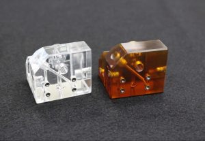
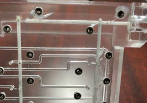
An additional consideration for material selection is the optical clarity desired in your finished part. Some manifold designers want a relatively transparent material with a high quality finish to allow for optical sensors or visual inspection of the fluids and potential contamination during operation. CMG offers vapor polishing to create a glass-like finish on manifolds where optical clarity is important.
Step 4: Define the Constraints on Size, Operational Planes, and Production Method
Step 4 is easier than it sounds. How much space is there in your device for a manifold assembly? What is the maximum length x width x height that this manifold and the attached components can occupy? Will any of the manifold sides / planes sit flush against another surface that will prevent them from having input / output ports on that face? How much room is allowed for pumps or valves that are mounted to the manifold?
Define the planes that would allow optimum access to inlet and outlet ports. Ease of access for service and replacement of components mounted to the manifold should also be taken into consideration. For manufacturing cost savings, limit working planes to as few as possible.
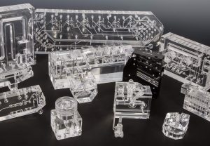
The production method will most likely be defined by the material selection. Diffusion bonding allows for multiple layers of plastic to be machined and bonded together, creating unique flow paths that can overlap, curve, and split in designs that cannot be achieved through traditional “machining-only” techniques.
While diffusion bonding is extremely useful for design flexibility, it is limited to acrylic (PMMA) and Ultem (PEI) materials. If the temperature range, pressure values, or chemicals utilized in your system require a more advanced polymer, such as PEEK or Polysulfone, then your manifold cannot be diffusion bonded and the design will be constrained to a layout that can be achieved through plastics machining.
Step 5: Choose Connection Methods for Inlet & Outlet Ports
One of the benefits of a performance plastic manifold is that threading can be tapped / machined directly into the external ports for a connection fitting. You get to choose how to connect your inputs (water, cleaning solution, reagents) to your manifold. Ideally, you will consider one of many catalog options in the industry that are readily available with standard sizes and threading, such as ¼-28, 10-32, or M6. Component manufacturers commonly define surface finishes for connection ports – their specifications will indicate the ideal interface surface finish to ensure proper sealing.
Many items can be connected or mounted via a threaded ultrasonic insert or press-fit option. These inserts provide a stronger, more secure hold on hardware, especially for bulky surface-mounted components. Threaded ports directly in the plastic are certainly an option but optimum performance is achieved with ultrasonic inserts.
Step 6: Select the Optimal Channel Shape & Size for Flow Paths
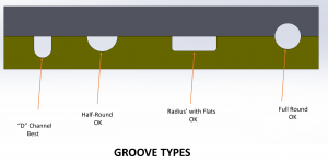
Channels come in many shapes and sizes. In a “machining-only” manifold, the holes or bores will be a full round shape as required by the cutting tool creating the hole. In a diffusion bonded manifold, channels can be full round, “D” shaped, half-round, or even a radius with flats (squared) “|_|” along the flow path. Some situations may dictate or prefer one channel shape to another.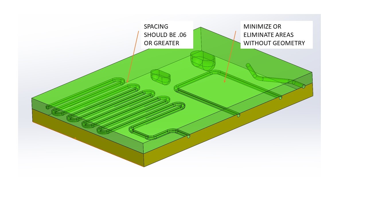
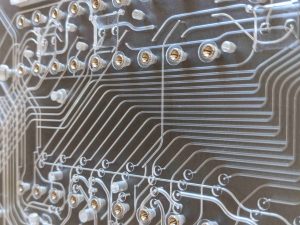
As the manufacturer of your manifold, it is desirable to have oversized flow connections in the manifold flow path. Where one drilled hole or channel intersects another, an oversized connection point reduces the risk of misalignment and improves the manufacturability of the design. An easier target for machinists equates to reduced manufacturing time and an even lower scrap rate, which provides you with a better price on your manifolds.
Ask an expert at CMG if you have questions or concerns with your channel design. If you have made it this far, you are most likely ready to contact us for a quote and design for manufacturing feedback.
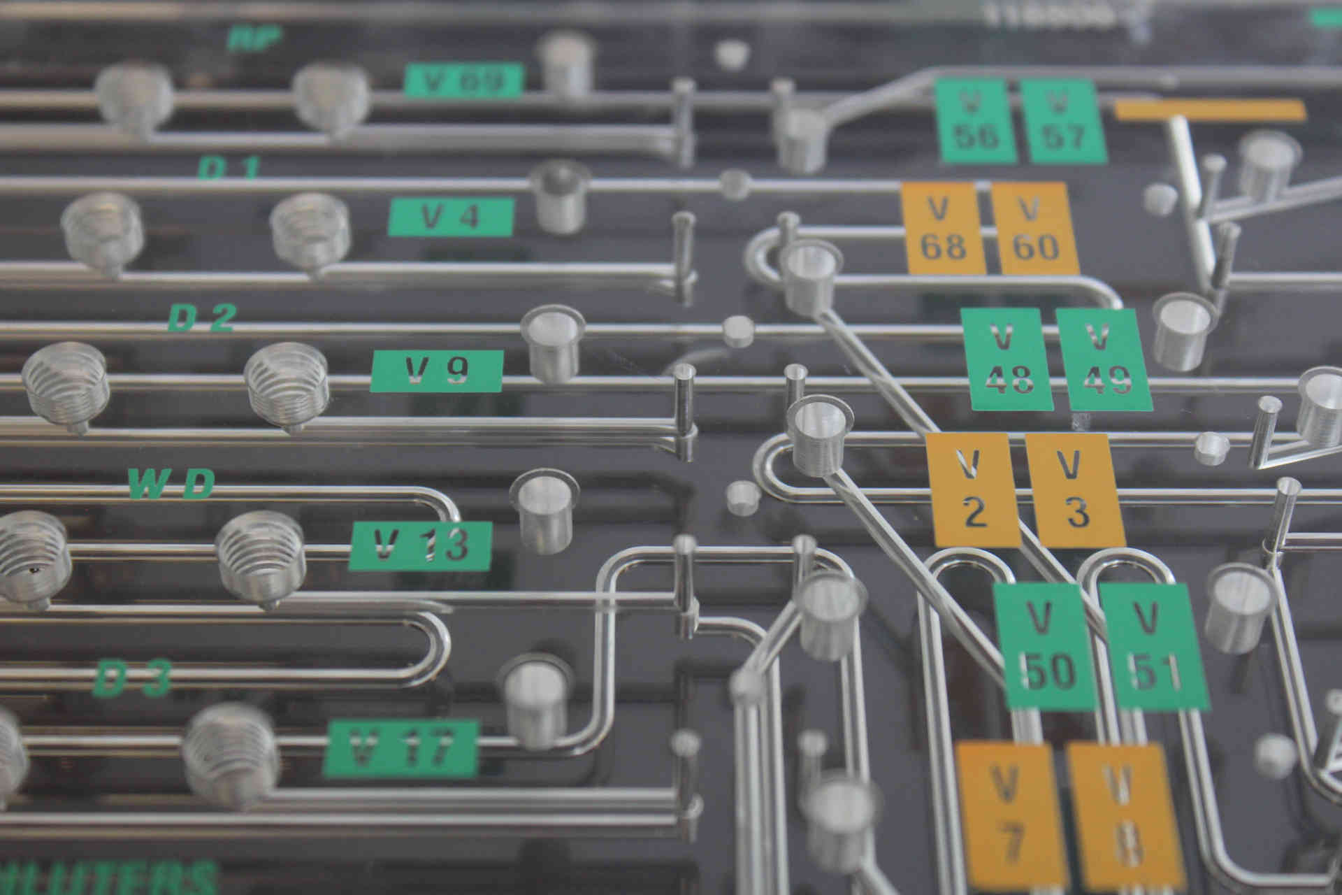
Step 7: Determine if Labeling, Engraving, or Part Marking is Required
Laser engraving information on the surface of the manifold is a common practice to improve traceability and provide useful instructions to operators who install, use, or service the fluidic device. Serialized part numbers help track inventory and troubleshoot device issues. Labels on connection ports and mounting locations help reduce errors, speed up installation, and are very helpful when servicing the device. CMG offers laser engraving to rapidly and permanently mark manifolds with this type of useful information. The engravings can even be color-coded with permanent ink for added visual cues.
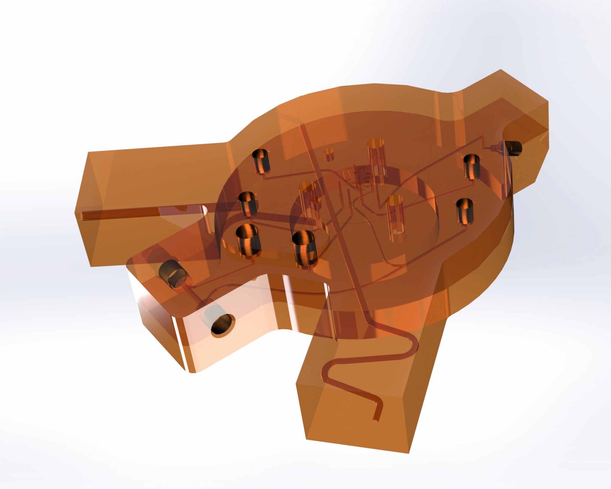
Step 8: Put it all Together in a CAD Model
In order to provide a quote and manufacture a diffusion bonded manifold, we require a CAD model and an engineering drawing with tolerances. If this is not your expertise or you need to focus on other engineering priorities, don’t worry! We provide this service as well. If you have followed this article from Step 1 through Step 7, then you most likely already have all of the information we need to create a solid model and print with tolerances. Congratulations! You have successfully designed a diffusion bonded manifold. Contact CMG when you are ready to take the next steps with your design.
